Key people in Orion history: The Inventor
Dr. Stanislaw Ulam
Patent British #877,392
Nuclear propelled vehicle, such as a rocket
Inventor: Applicant: ATOMIC ENERGY COMMISSION
EC: F42B12/58; G21D5/02; (+1) IPC:
Publication info: GB877392 - 1961-09-13
Abstract of GB877392
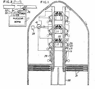
877,392. Self-propelled rockets. UNITED STATES ATOMIC ENERGY COMMISSION. Feb. 17, 1960 [March 3, 1959], No. 5595/60. Class 9(2). To propel a vehicle 11 such as a rocket, nuclear bombs are ejected and exploded at timed intervals, a series of thrusts being imparted to the rocket through plastic sheets 21. Each bomb has a housing 17 held in a rack 19 by bell-cranks 23 operatively connected to the plungers 28 of pneumatic cylinders 29. Each cylinder is connected through a valve 30 to a gas reservoir 31, each valve being hermetic- ally sealed until forced open by explosive means as in U.S.A. Specification 2,515,068, the valves being electrically connected to a cam-operated rotary switch 41 controlled by a timer 39. Each bomb housing is connected by a flexible steel cable 35 to a sheet 21 surrounding a slotted guide 38. Thus, as the detonators of the valves are fired successively, the bomb housings are successively ejected. A latch 22 projecting from one of the supporting bell-cranks moves a toggle switch 26 on the bomb 17 as it is ejected, to start a timer 50 controlling a cam-operated switch 52, so that, a predetermined time after ejection, the switch 52 closes and fires a detonator 53. On explosion of the bomb by the detonators 53 the associated plastic sheet 21 is vaporised and the vapour produced propels the rocket.
---

---
Description of GB877392
Desc/Clms Page number 1
Nuclear Propelied Vehicle, such as a Rocket We, UNITED STATES ATOMIC ENERGY COMMISSION, Germantown, Maryland, United States of America, a duly constituted agency of the Government of the United States of America, established by the Atomic Energy Act of 1946 (Public Law 585) and the Atomic Energy Act of 1954 (Public Law 703), do hereby declare the invention for which we pray that a patent may be granted to us and the method by which it is to be performed, to be particularly described in and by the following statement:-
quence, the embodiment shown makes use of simple mechanical and electral mechanisms. Each bomb housing 17 is maintained in a fixed position in the rack 19 by the inner ends 20 of a. pair of bell crank members 23. The bell crank members are pivoted on substantial journal elements 25 affixed to the rack rails. The ends of the inner arms of the bell crank members engage a capstan- shaped member 27 affixed to the top of bomb housing 17. The outer end 24 of each bell crank member 23 is engaged by the outer end of plunger 28 of pneumatic cylinder 29. These pneumatic cylinders 29 are of the type which remain locked in retracted position until a gaseous or fluid medium is applied under pressure in a manner well known in the art. Connected to the lower- end of each pneumatic cylinder, through an explosive actuated valve 30, is a high pressure gaseous storage chamber 31. Valve 30 is of a type which is hermeticaLy closed until spontaneously opened by an explosive mechanism which is electrically operated. Such explosively operated valves are known in the art.
It follows from the foregoing that the operation of the valves associated with the pneumatic cylinders holding any one bomb in place will cause the rapid ejection of the bomb along the rails 19 and out through the bottom of the vehicle. The lowermost pneumatic cylinder and its associated bell crank is shown in the drawing in its operated condition. It is seen that the inner arm of the bell crank is now folded down parallel with the rack members and out of the way of the path of succeeding bombs. Each bomb is connected by a flexible steel cable 35 to a respective one of the plastic sheets 21. The length of the cable is preferably of the order of 40 metres and most of the cable is stored in a coil above the bomb housing as shown in Figure 3. In order that the ejecting bomb will symmetrically eject its associated plastic sheet, the ends of the cables connected to the plastic sheet are engaged therewith through stuff reinforcing members or ribs 37.
The plastic sheets 21 are supported in position by protrusions 36 axed to or integral with the vehicle wall inner- surface. A sectored cylindrical member 38 provides an inner guide and/or support for the plastic sheets. The slots 381 provide a guide for the cables 35.
The bombs are successively ejected with intervening intervals, preferably of about one second. The timing intervals are controlled by timer 39 which may be spring wound or electrically driven and which is mechanically linked to electrical contacting switch 41. The rotor 42 of switch 41 is in series with a source of electrical power 43 al-id the bomb rack rails 19. Successive contacts of the switch are connected to the detonators in the valves associated with successive bombs. It has been found to be desirable to detonate each bomb when it is at a distance of approximately 50 metres from the base of the rocket. Referring to Figure 2, it is seen that provision is n-lade for arming the bomb at the instant it is ejected from the rocket so that it will be fired at the selected distance. The inner end 20 of one of the sustaining bell cranks is provided with a latch projection 22 which engages the handle 261 of an arming toggle switch 26 when the bomb is ejected from the rocket. The setting of the toggle switch into armed condition starts timer 50. Timer 50, in turn, controls a cam-operated switch 52 which fires detonator 53 of the bomb after the preselected interval after the bomb is ejected from the rocket.
In order to facilitate the ejection of the nuclear bomb housing with its associated equipment from the rocket housing without any possibility of jamming, rollers 60 are journalled in flanges 62 axed to the edges of the bomb housing and engage the vertical racks in wheel and track fashion so that the motion of the bomb housing is free and unhindered.
From the foregoing it is seen that an effective yet simple nuclear rocket propulsion system has been described. It is understood that the embodiment shown and described is for the purpose of illustration and explanation and is not intended to prevent the application of other techniques which would be obviously applicable to carrying out the spirit of this invention.
---
Claims of GB877392
WHAT WE CLAIM IS:- 1. A nuclear propelled rocket ship com- prising a housing having a nose cone front portion and a cylindrical body portion, at least a pair of rail members supported parallel to the axis of said rocket and spaced one from the other symmetrically about the said axis of the rocket, a plurality of nuclear bomb housed within said rocket, means for individually releasably supporting said bombs between said rails, a RTI plurality of sheets of plastic material having a configuration similar to that of the cross-sectional profile of the rocket housed in the nether portion of said rocket, resilient tensile members connecting the bombs to respective ones of said plastic sheets and having a length of approximately 40 metres, means for ejecting said bombs in sequence, means responsive to the ejection of each of said bombs for arming the same whereby it will detonate at selected distance from said rocket. 2. A nuclear propelled rocket ship comprising a housing having a nose cone portion and a cylindrical body portion, means within said body portion for detachably supporting a plurality of nuclear fission bombs, means for ejecting said bombs at selected intervals, a plurality of plastic material sheets having a
Desc/Clms Page number 3
boundary configuration substantially like that of the interior of the cylindrical body portion interior and being detachably supported within the interior body portion proximate the nether end thereof, RTI tensile members of the order of length of 40 metres connecting each of said bombs with respective ones of said plastic material sheets, timing means within each of said bombs, means responsive to the operation of the ejection means for starting the timing means whereby each of said bombs will be detonated at a preselected time lapse after ejection. 3. A nuclear propelled rocket ship as claimed in Claim 1 substantially as described with reference to the accompanying drawings.
---
---
His related publications
Space Propulsion
On a method of propulsion of projectiles by means
of external nuclear explosions (with C. J. Everett).
Los Alamos Scientific Laboratory report LAMS-
1955, 1955.
Statement before the U.S. House of Representatives.
Hearings on Astronautics and Space Exploration.
85th Congress, 2nd session, April 15–May
12, 1958.
Nuclear propelled vehicle, such as a rocket (with
C. J. Everett). British Patent 877,392, 1961.
The future of nuclear energy in space: A panel
discussion sponsored by the Aerospace Division,
American Nuclear Society, at the 1963 winter
meeting in New York City, N. Y. on November
20, 1963 (with F. deLuzio, W. von Braun, M.
Hunter, and I. Asimov), edited by R. F. Trapp.
Also in Nuclear News, July 1964.
The Orion project.** Nuclear News, January 1965,
25–7.
Patent British #877,392
Nuclear propelled vehicle, such as a rocket
Inventor: Applicant: ATOMIC ENERGY COMMISSION
EC: F42B12/58; G21D5/02; (+1) IPC:
Publication info: GB877392 - 1961-09-13
Abstract of GB877392
877,392. Self-propelled rockets. UNITED STATES ATOMIC ENERGY COMMISSION. Feb. 17, 1960 [March 3, 1959], No. 5595/60. Class 9(2). To propel a vehicle 11 such as a rocket, nuclear bombs are ejected and exploded at timed intervals, a series of thrusts being imparted to the rocket through plastic sheets 21. Each bomb has a housing 17 held in a rack 19 by bell-cranks 23 operatively connected to the plungers 28 of pneumatic cylinders 29. Each cylinder is connected through a valve 30 to a gas reservoir 31, each valve being hermetic- ally sealed until forced open by explosive means as in U.S.A. Specification 2,515,068, the valves being electrically connected to a cam-operated rotary switch 41 controlled by a timer 39. Each bomb housing is connected by a flexible steel cable 35 to a sheet 21 surrounding a slotted guide 38. Thus, as the detonators of the valves are fired successively, the bomb housings are successively ejected. A latch 22 projecting from one of the supporting bell-cranks moves a toggle switch 26 on the bomb 17 as it is ejected, to start a timer 50 controlling a cam-operated switch 52, so that, a predetermined time after ejection, the switch 52 closes and fires a detonator 53. On explosion of the bomb by the detonators 53 the associated plastic sheet 21 is vaporised and the vapour produced propels the rocket.
---
---
Description of GB877392
Desc/Clms Page number 1
Nuclear Propelied Vehicle, such as a Rocket We, UNITED STATES ATOMIC ENERGY COMMISSION, Germantown, Maryland, United States of America, a duly constituted agency of the Government of the United States of America, established by the Atomic Energy Act of 1946 (Public Law 585) and the Atomic Energy Act of 1954 (Public Law 703), do hereby declare the invention for which we pray that a patent may be granted to us and the method by which it is to be performed, to be particularly described in and by the following statement:-
quence, the embodiment shown makes use of simple mechanical and electral mechanisms. Each bomb housing 17 is maintained in a fixed position in the rack 19 by the inner ends 20 of a. pair of bell crank members 23. The bell crank members are pivoted on substantial journal elements 25 affixed to the rack rails. The ends of the inner arms of the bell crank members engage a capstan- shaped member 27 affixed to the top of bomb housing 17. The outer end 24 of each bell crank member 23 is engaged by the outer end of plunger 28 of pneumatic cylinder 29. These pneumatic cylinders 29 are of the type which remain locked in retracted position until a gaseous or fluid medium is applied under pressure in a manner well known in the art. Connected to the lower- end of each pneumatic cylinder, through an explosive actuated valve 30, is a high pressure gaseous storage chamber 31. Valve 30 is of a type which is hermeticaLy closed until spontaneously opened by an explosive mechanism which is electrically operated. Such explosively operated valves are known in the art.
It follows from the foregoing that the operation of the valves associated with the pneumatic cylinders holding any one bomb in place will cause the rapid ejection of the bomb along the rails 19 and out through the bottom of the vehicle. The lowermost pneumatic cylinder and its associated bell crank is shown in the drawing in its operated condition. It is seen that the inner arm of the bell crank is now folded down parallel with the rack members and out of the way of the path of succeeding bombs. Each bomb is connected by a flexible steel cable 35 to a respective one of the plastic sheets 21. The length of the cable is preferably of the order of 40 metres and most of the cable is stored in a coil above the bomb housing as shown in Figure 3. In order that the ejecting bomb will symmetrically eject its associated plastic sheet, the ends of the cables connected to the plastic sheet are engaged therewith through stuff reinforcing members or ribs 37.
The plastic sheets 21 are supported in position by protrusions 36 axed to or integral with the vehicle wall inner- surface. A sectored cylindrical member 38 provides an inner guide and/or support for the plastic sheets. The slots 381 provide a guide for the cables 35.
The bombs are successively ejected with intervening intervals, preferably of about one second. The timing intervals are controlled by timer 39 which may be spring wound or electrically driven and which is mechanically linked to electrical contacting switch 41. The rotor 42 of switch 41 is in series with a source of electrical power 43 al-id the bomb rack rails 19. Successive contacts of the switch are connected to the detonators in the valves associated with successive bombs. It has been found to be desirable to detonate each bomb when it is at a distance of approximately 50 metres from the base of the rocket. Referring to Figure 2, it is seen that provision is n-lade for arming the bomb at the instant it is ejected from the rocket so that it will be fired at the selected distance. The inner end 20 of one of the sustaining bell cranks is provided with a latch projection 22 which engages the handle 261 of an arming toggle switch 26 when the bomb is ejected from the rocket. The setting of the toggle switch into armed condition starts timer 50. Timer 50, in turn, controls a cam-operated switch 52 which fires detonator 53 of the bomb after the preselected interval after the bomb is ejected from the rocket.
In order to facilitate the ejection of the nuclear bomb housing with its associated equipment from the rocket housing without any possibility of jamming, rollers 60 are journalled in flanges 62 axed to the edges of the bomb housing and engage the vertical racks in wheel and track fashion so that the motion of the bomb housing is free and unhindered.
From the foregoing it is seen that an effective yet simple nuclear rocket propulsion system has been described. It is understood that the embodiment shown and described is for the purpose of illustration and explanation and is not intended to prevent the application of other techniques which would be obviously applicable to carrying out the spirit of this invention.
---
Claims of GB877392
WHAT WE CLAIM IS:- 1. A nuclear propelled rocket ship com- prising a housing having a nose cone front portion and a cylindrical body portion, at least a pair of rail members supported parallel to the axis of said rocket and spaced one from the other symmetrically about the said axis of the rocket, a plurality of nuclear bomb housed within said rocket, means for individually releasably supporting said bombs between said rails, a RTI plurality of sheets of plastic material having a configuration similar to that of the cross-sectional profile of the rocket housed in the nether portion of said rocket, resilient tensile members connecting the bombs to respective ones of said plastic sheets and having a length of approximately 40 metres, means for ejecting said bombs in sequence, means responsive to the ejection of each of said bombs for arming the same whereby it will detonate at selected distance from said rocket. 2. A nuclear propelled rocket ship comprising a housing having a nose cone portion and a cylindrical body portion, means within said body portion for detachably supporting a plurality of nuclear fission bombs, means for ejecting said bombs at selected intervals, a plurality of plastic material sheets having a
Desc/Clms Page number 3
boundary configuration substantially like that of the interior of the cylindrical body portion interior and being detachably supported within the interior body portion proximate the nether end thereof, RTI tensile members of the order of length of 40 metres connecting each of said bombs with respective ones of said plastic material sheets, timing means within each of said bombs, means responsive to the operation of the ejection means for starting the timing means whereby each of said bombs will be detonated at a preselected time lapse after ejection. 3. A nuclear propelled rocket ship as claimed in Claim 1 substantially as described with reference to the accompanying drawings.
---
---
His related publications
Space Propulsion
On a method of propulsion of projectiles by means
of external nuclear explosions (with C. J. Everett).
Los Alamos Scientific Laboratory report LAMS-
1955, 1955.
Statement before the U.S. House of Representatives.
Hearings on Astronautics and Space Exploration.
85th Congress, 2nd session, April 15–May
12, 1958.
Nuclear propelled vehicle, such as a rocket (with
C. J. Everett). British Patent 877,392, 1961.
The future of nuclear energy in space: A panel
discussion sponsored by the Aerospace Division,
American Nuclear Society, at the 1963 winter
meeting in New York City, N. Y. on November
20, 1963 (with F. deLuzio, W. von Braun, M.
Hunter, and I. Asimov), edited by R. F. Trapp.
Also in Nuclear News, July 1964.
The Orion project.** Nuclear News, January 1965,
25–7.

2 Comments:
I was looking for information on Key people in Orion history: The Inventor and before ending in your blog I watched like 10 sites about viagra online, the web is full with that topic. But anyways the info on your site help me very much, thanks for the post and have a nice day.
Is there any further reading you would recommend on this?
Amela
pneumatic cylinder
Post a Comment
<< Home